Overview
The purpose of this document is to quickly get you up and running using the capabilities offered by Inventek System’s AT Command Set and eS-WiFi modules. In order to demonstrate the available features we will be using an eS-WiFi Evaluation Board that provides easy connectivity to the module. We will provide an overview of the board’s interface options as well as a tutorial on how to use the AT command set to enable wireless connectivity in your embedded design.
There are several different ways that the eS-WiFi modules can be used to interface with systems on a wireless network. When attaching to an existing network the module can assume the role of either a network server to which clients connect or a network client that connects to an existing server. In addition to joining an existing wireless network, the eS-WiFi module can provide its own wireless network by serving as an access point to which devices can join in order to communicate with the module. When functioning as an access point the module can still serve as client or server.
This document will be organized as follows:
1. eS-WiFi Evaluation Board Overview
2.1 Join an Existing WiFi Network
4. Connect to a Network System
4.1 Operating the eS-WiFi Module as a Client
4.2 Operating the eS-WiFi Module as a Server
5. Send Data to a Network System
6. Receive Data from a Network System
7. Communicate with Multiple Network Systems
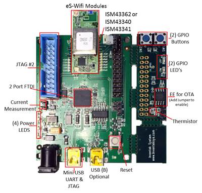
1. eS-WiFi Evaluation Board Overview
The picture below shows the evaluation board and highlights a number of its components. There are two primary ways to communicate with the board: through a USB UART or through a Serial Peripheral Interface (SPI) bus connection. The UART connection is lower speed and is made by connecting a cable between the mini-USB port and a computer’s USB port. A SPI connection is higher speed and is made by wiring several of the pins in the break out header to a micro-controller that supports SPI or provides suitable GPIO lines.
2. Joining a Network
One of the first things you will wish to do when bringing up an eS-WiFi module is to connect to a wireless network. The eS-WiFi module provides the capability to join an existing wireless network or to provide its own network by operating as an access point. The operating mode that you choose will depend upon your own particular use case.
We will first discuss connecting the module to an existing wireless network and then discuss the process of operating as a wireless access point.
2.1 Join an Existing WiFi Network
The eS-WiFi module provides multiple ways to join a wireless network. One method is to use the A0 command which creates an access point with the SSID eS-WiFi_AP_XXXXXXXXXX where the string of Xs is the MAC address of the module. Once connected to this access point you can open a web browser and navigate to any URL or the address 192.168.10.1 to view the configuration page shown below. This page displays a listing of all the wireless networks that the eS-WiFi module can detect. To join one of these networks you must click the join button and provide a password if prompted.
The other way to join a wireless network is to do so programmatically using AT commands. The following table shows the most commonly used connection commands that are available to you.
| Command | Operation | Options | Comments |
|---|---|---|---|
| C? | Show Settings | ||
| C0 | Join Network | ||
| C1 | Set SSID | <SSID> | |
| C2 | Set Passphrase | <Passphrase> | |
| C3 | Set Security Type | 0-4 | 0 = Open1 = WEP
2 = WPA 3 = WPA2-AES 4 = WPA2 Mixed |
| C4 | Enable DHCP | 0-1 | 0 = False1 = True |
| C5 | Set IP Version | 0-1 | 0 = IPv41 = IPv6 |
| C6 | Set IP Address | XXX.XXX.XXX.XXX | |
| C7 | Set IP Mask | XXX.XXX.XXX.XXX | |
| C8 | Set Default Gateway | XXX.XXX.XXX.XXX | |
| C9 | Set DNS Server 1 | XXX.XXX.XXX.XXX | |
| CD | Disconnect from Network |
The simplest configuration is to join a network and use DHCP to assign your module an IP Address. The following commands will join the module to your network. In order to execute these commands you will need to provide the network’s SSID and password. If you do not know these values please contact your network administrator.
C1=YourNetworksSSID         Set the SSID for your network
C2=YourPassword             Set the password for your network
C3=4                        Utilize WPA2 Mixed mode security
C4=1                        Enable DHCP
C0                          Join the network
A more advanced configuration would involve manually entering the module’s IP address and associated network settings. The following commands will set these values and then join the network.
C1=YourNetworksSSID         Set the SSID for your network
C2=YourPassword             Set the password for your network
C3=4                        Utilize WPA2 Mixed mode security
C4=0                        Disable DHCP
C6=192.168.1.10             Set the module's IP address
C7=255.255.255.0            Set the module's network mask
C8=192.168.1.1              Set the module's default gateway
C9=192.168.1.1              Set the module's primary DNS server
C0                          Join the network
For either configuration, if the join process was successful you will see the message
[JOIN ] YourNetworksSSID,XXX.XXX.XXX.XXX,0,0
OK
>
appear on your terminal. In this output, the text YourNetworksSSID will be replaced with the value that you provided and the value XXX.XXX.XXX.XXX will be replaced with the DHCP assigned IP Address.
In the event the join process was unsuccessful, however, you will see the message
[JOIN ] YourNetworksSSID
[JOIN ] Failed
ERROR: Unknown Error
Usage: C0
>
If you see this output please check the settings you entered and try again.
2.2 Create a New WiFi Network
If a wireless network is not available for your use it is possible to configure the eS-WiFi module to serve as an access point.
| Command | Operation | Options | Comments |
|---|---|---|---|
| A? | Show Settings | ||
| A0 | Start Access Point | ||
| A1 | Set Security Mode | 0-4 | 0 = Open1 = Invalid
2 = WPA 3 = WPA2 4 = WPA + WPA2 |
| A2 | Set Security Key | ||
| AA | Get AP DHCP Cached Address(es) | ||
| AC | Set AP Channel | 0-13 | |
| AD | Activate AP Direct Connect Mode | ||
| AE | Exit AP Direct Connect Mode | ||
| AL | Set AP DHCP Lease Time | 0-255 | C2.4.00 = 30 min
1-255 = 1-255 hour(s) C2.5.0 0 = 30 min 1-254 = 1-254 hour(s) 255 = 136 years |
| AR | Get RSSI of AP Client | ||
| AS | Set SSID | 0/1,SSID | 0 = No MAC1 = Use MAC |
| AT | Set Maximum Number of Client | 1-3 |
The minimum configuration necessary to start an access point is the security mode, password and SSID. The following commands set these values and start the access point.
A1=2
A2=password
AS=0,YourNetworksSSID
AD
The result of the AD command will be the output
[AP ] SSID: YourNetworksSSID MAC: XX:XX:XX:XX:XX:XX,2,192.168.10.1
[WEB SVR] CSO Server Started
[JOIN ] !DIRECTCONNECT,192.168.10.1
>
3. Pinging a Host on the Network
Once you have joined a wireless network you may wish to run a very basic connectivity test to ensure that your link has been established correctly. The most widely used networking utility to test the reachability of a network host is Ping. This utility is supported in the AT Command Set with the following commands
| Command | Operation | Options | Comments |
|---|---|---|---|
| T? | Show Settings | ||
| T0 | Ping | ||
| T1 | Set Target Address | XXX.XXX.XXX.XXX | |
| T2 | Set Repeat | 0-65535 | 65535 = Continuous(CTRL-C to stop) |
| T3 | Set Delay | 0-5000 | Time in ms |
The example below shows how to ping a host using the eS-WiFi module.
T1=192.168.1.26            Set the target IP address
T2=0                       Only send a single ping
T3=0                       No delay between pings
T0                         Send ping
If the network host is reachable you will see output
192.168.1.26,1
OK
>
where the number following the comma is the round trip time in milliseconds that was measured. If the network host is not reachable you will see the output
192.168.1.26,Timeout
OK
>
4. Connect to a Network System
Once joined to a wireless network the eS-WiFi module is able to communicate with systems on the network by assuming the role of either a network client or a network server. The only difference between the two operational modes is in which system initiates the connection as the commands to send and receive data are identical in both cases.
The table below lists the AT commands used in establishing a connection between network systems.
| Command | Operation | Options | Comments |
|---|---|---|---|
| P? | Show Settings | ||
| P0 | Show Settings | 0-3 | |
| P1 | Set Communication Socket | 0-3 | 0 = TCP1 = UDP |
| P2 | Local Port | 0-65536 | |
| P3 | Remote Host IP Address | XXX.XXX.XXX.XXX | |
| P4 | Remote Port | 0-65536 | |
| P5 | Stop/Start Server | 0-1,10-11 | 0 = stop1 = start
10 = multi-accept restart 11 = multi-accept start |
| P6 | Stop/Start Client | 0-1 | 0 = stop1 = start |
4.1 Operating the eS-WiFi Module as a Network Client
Having joined a wireless network and established that basic connectivity exists between the eS-WiFi module and a server on the network we will want to connect to that server in order to send and receive data. The following command sequence will connect an eS-WiFi module to the server located at the specified port and IP address using the TCP transport protocol.
P1=0                        TCP
P3=192.168.1.10             Server IP address (D0 will perform a DNS lookup on and update P3 automatically)
P4=8022                     Server port
P6=1                        Start the client
4.2 Operating the eS-WiFi Module as a Network Server
In order to operate as a network server we must first configure the protocol and port number that the server will be listening to.
P1=0                        TCP
P2=8022                     Local port
After setting up the local port we will use the P5 command to control the network server. There are two ways to use this command to begin accepting connections as the commands P5=1 and P5=11 will both start the server. The command P5=11, however, is designed to accept multiple successive connections. If you issue this command you may close the connection and then immediately begin listening for new connections on that port by issuing the single command P5=10. This is to say that the command sequence
P5=11
… data is exchanged …
P5=10
is equivalent to the sequence
P5=1
… data is exchanged …
P5=0
P5=1
The following output is generated by the eS-WiFi module when a P5=1 command is issued
[TCP TSK] Setup
[TCP SVR] Waiting on connection ...
OK
>
Similarly, when a P5=11 command is issued the system will output the following
[TCP TSK] Multi-Accept Setup
[TCP SVR] Waiting on connection ...
OK
>
The output from either P5 commands shown above does not give any indication as to whether a connection to the server has been established. In order to determine if a client has connected to the server we can issue a P? command and parse the output. The output generated by a P? command will be a comma separated list. From left to right the fields of this list are
Protocol
Client IP
Address
Local Port
Host IP
Address
Remote Port
TCP Server
UDP Server
Backlogs
Accept Loop
Read Mode
TCP KA
TCP KA TTI
The following string shows the output from the P? command when no client has connected
0,0.0.0.0,8022,0.0.0.0,0,1,0,1,0,0,0,7200000
We see that the second entry in the comma separated list is 0.0.0.0 which tells us that no client has connected. If the P? command were to return the string
0,192.168.1.98,8022,0.0.0.0,51488,1,0,1,1,0,1,500
we could conclude that a client at address 192.168.1.98 had connected to our server.
5. Sending Data
Once a connection has been established between the eS-WiFi module and another system on the network we will want to send data. The table below lists the AT commands available for sending data.
| Command | Operation | Options | Comments |
|---|---|---|---|
| S? | Show Settings | ||
| S0 | Send Data | ||
| S1 | Set Data Packet Size | 1-1460 | Bytes |
| S2 | Transmit Timeout | 0-30000 | ms |
| S3 | Send Data with PacketSize | 1-1460 | XXXX=PacketSize\r |
There are two commands which will send data from the eS-WiFi module: S0 and S3. The difference between the two commands is that S3 sets the packet size and sends data in a single command issuance. The command sequence
S1=5
S0\r12345
is effectively equivalent to
S3=5\r12345
as both will generate the output
5
OK
>
where 5 is the number of bytes transmitted. If you were to provide greater than 5 bytes worth of data the system would only transmit the first 5 provided. If you were to provide fewer than 5 bytes the system would error and provide output similar to the following
TX Data mismatch, 3 bytes received!
> ERROR: Unknown Error
Usage: S0\r<Bytes>
>
or
TX Data mismatch, 3 bytes received!
> ERROR: Unknown Error
Usage: S3 <0001 – 1460>\r<Bytes>
>
6. Receiving Data
In addition sending data to a system on the network we will want to receive data from network systems. The table below shows the commands that you will use to read data that is sent to you from the server.
| Command | Operation | Options | Comments |
|---|---|---|---|
| R? | Show Settings | ||
| R0 | Receive Data | ||
| R1 | Set Data Packet Size | 1-1460 | Bytes |
| R2 | Receive Timeout | 0-30000 | ms |
| R3 | Receive Mode | 0-1 | 0 = Normal1 = No Timeout/No Data Message |
Reading data is accomplished using the commands R1 and R0. The command R1 is responsible for setting the expected input packed size. The command R0 is responsible for reading in a packet worth of data from the receive buffer. It is worth noting that any data beyond a packet’s worth will remain in the buffer and will be read out the next time a call to R0 is made. If the amount of available data is less than a packet’s worth the R0 command will return that much data emptying the buffer.
For example, if the receive buffer was empty until the server transmitted the string “helloworldtesting12345” the following output would be generated
R1=5

R0

helloworld
OK
>

R0

testing123
OK
>

R0

45
OK
>
If no data was available in the receive buffer the command R0 would generate the output
OK
>
And if by chance the eS-WiFi module was not connected to a server issuing an R0 command would generate the output
-1
ERROR: Unknown Error
Usage: R0
>
7. Connecting to Multiple Systems
The examples we have seen thus far have involved connecting the eS-WiFi module to a single network system. The eS-WiFi module does, however, allow for a total of 4 connections to be active simultaneously. Multiple connections are managed by using the P0 command to switch between the available network links. Once the desired socket has been selected you are able to read and write using the commands we have previously described. It was not necessary to select a socket in the prior examples as the system defaults to the P0=0 setting.
The following command sequence illustrates how to establish multiple server connections. After connecting the code then attempts to read from and write to each independently.
Client+Multiple+Sockets + Flow
P0=0
P3=192.168.1.25
P4=1023
P6=1

P0=1
P3=192.168.1.48
P4=8088
P6=1

P0=2
P3=192.168.1.20
P4=8088
P6=1

P0=0
R0
S3=10\rCOMMAND=11

P0=1
R0
S3=10\rCOMMAND=14

P0=2
R0
S3=10\rCOMMAND=18
As before, if a connection is not established the R0 command will reply with the sequence
-1
ERROR: Unknown Error
Usage: R0
>
and the S3 command will reply with the sequence
[TCP TX] No Active Socket!
ERROR: Unknown Error
Usage: S3 <0001 – 1460>\r<Bytes>
>
8. Saving your Configuration
The eS-WiFi module contains flash memory that can be used to save your working configuration. The memory available for saving system settings has been partitioned into two regions:
1. Factory Space
2. User Space
We recommend that customers save their settings in the user configuration section as this allows for a quick recovery in the event that problems arise. Further, preserving the factory space allows you to performing a full system restore which will erase the contents of User Space and write in the factory defaults allowing the module to start in a known state.
The table below shows the commands that are available for saving and restoring settings.
| Command | Operation | Options | Comments |
|---|---|---|---|
| Z? | Show Settings | ||
| Z0 | Reset to Factory Defaults | ||
| Z1 | Save Current Settings | ||
| Z2 | Clear Saved Settings | ||
| Z3 | Set Factory/User Space | 0-1 | 0 = Factory Space1 = User Space |
Once you have configured the eS-WiFi module to connect to your network you can save the settings by executing the command Z1 which will save to User Space by default. Once saved these settings will be in place if the module is restarted.