Below is the IWIN AT Commands users manual.
Downloads:
IWIN AT COMMAND Quick Start guide.pdf
1. Introduction
1.1 Scope
The scope of this document is to introduce users to Inventek System’s AT Command Set called IWIN for the eS-WiFi Module product, and to explain how to take advantage of the AT Command Set for Wi-Fi Communications.
When you purchase the Inventek module we have programmed our latest firmware for either UART,SPI or USB onto the module. When you order your production parts, you need to specify your firmware build that you have qualified, details are found in the product specifications.
The AT Command set is very simple to use and the default firmware is set for UART, 115K baud and you can download a free PC demo software program from the Inventek web site to exercise the module.
1.2 AT Command Usage in the User Manual is shown as
Usage: < AT Command > < optional ‘=’ > < data if ‘=’ is used > < Carriage Return (CR) >
or
< AT Command > < CR >
And default values are show as
Default: < AT Command > = < Value >
1.3 Supported Product Versions
This document covers the following currently available eS-WiFi modules:
ISM43362-M3G-L44, ISM43362-M3G-EVB, ISMART43362
ISM43340-M4G-L44-10, ISM43340-M4G-EVB, ISMART43340
ISM4343-M4G-L54, ISM4343-M4G-EVB, ISMART4343
ISM43903-R48-L54, ISM43903-R48-EVB, ISMART43903
ISM43907-L170, ISM43907-EVB
1.4. AT Command Set
In the early 1980’s, Hayes Microcomputer Products, Inc. was one of the first modem manufactures to use an ‘AT’ type Command Set to control operations of their modem products for communication over the Plain Old Telephone Service (POTS).
Since then a number of products have been developed for communications that use the ‘AT Command Set’ for device control.
‘AT’ is short for ‘AT’tention, and is used to get the attention of a device for set up and control of it’s functions. Normally, following the ‘AT’ command would be other letters and numbers that would control the functions associated with the command. For example, ‘ATDT1234567’ means ATtention modem Dial with Tone the number following the command, which in this case is 1234567.
Common practice today is to shorten the ‘AT’ command to just the function command, which using the example above, the shorten command to dial using tone for a number would be DT1234567.
1.4.1 Entering AT Commands
As mentioned above, it is common practice to drop the ‘AT’ in front of a device control command and just use the device control function command letters and number combinations. Inventek System has adopted this method for controlling the functions of the eS-WiFi module. In addition, Inventek System has added an ‘=’ to the command to delimit the command from its data. For example, the AT Command to set the eS-WiFi module’s IP Address would be ‘C6=127.0.0.1’ instead of ‘ATC6=127.0.0.1.
Also, a number of AT Commands for the eS-WiFi module only use a single letter or a single letter plus number to execute the command. For instance, ‘?’ will return available help information on the eS-WiFi module. While a ‘C0’ command would command the eS-WiFi module to joined a network.
The format for entering AT Commands is shown as follows:
< AT Command > < optional ‘=’ > < data if ‘=’ is used > < Carriage Return (CR) >
or
< AT Command > < CR >
All AT Commands must be followed by a <CR> to activate the command.
Empty string values for AT Commands are shown with ‘NONE’ in the User Manual.
The Supported character sets:
The eS-WiFi module supports sending and receiving binary or ASCII data.
All AT Commands must be in capital letters; however, data can contain binary bytes (0x00 to 0xFF).
1.4.2 eS-WiFi Command Formats
All AT commands sent to the module must be formatted as follows:
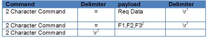
Note 1: \r = Carriage Return
For example:
P1=0\r
PK=1,3000\r
I?\r
All AT command responses from the module will follow this format:

Notes:
1: \r = Carriage Return, \n=New Line
3: sp =>space
For example:
- \r\nDATA\r\nOK\r\n>sp
- \r\nERROR\r\nUSAGE\r\n>sp
ASCII
- ODOADATA0D0AOKODOA3E20
- ODOADATA0D0AUSAGEODOA3E20
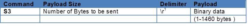
AT command to send Data can follow either of these formats:

Note 1: \r = Carriage Return
Note 1: \r = Carriage Return
For example:
S0DATA\r
S3=77\rDATA77byteslong
2 Hardware Interface and Module Operation
The eS-WiFi module supports RS-232 Serial Communications Universal Serial Bus (USB), and Serial Peripheral Interface Bus (SPI). A Micro-Controller or System Host can easily interface to the eS-WiFi module using one of the support hardware interfaces.
The eS-WiFi module has two modes of operation: Human Readable Mode and Machine Readable Mode. We recommend using Machine Readable for your application.
2.1 RS-232 Serial Communication
2.1.1 Data Mode
When the eS-WiFi module is interfaced serially, the serial interface needs to be configured for 8 bit data, no parity, and one stop bit — (8-n-1).
2.1.2 Flow Control
The eS-WiFi module doesn’t require or support Flow Control, so Flow Control should be ‘None’
2.1.3 Supported Baud Rates
The eS-WiFi module supports the following serial baud rates:
Basic Rates: 1200, 2400, 4800, 9600, 19200, 38400, 57600, 115200, 230400, 460800, 921600
Extended Rates: 1152000, 1382400, 1612800, 1834200, 2073600, 2304000, 2764800, 3686400, 3916800
2.1.4 Default Serial Configuration
The eS-WiFi module is shipped with the default serial configuration of 115,200 baud, 8 data bits, no party, and 1 stop bits.
Using the AT Commands you can change the default settings and save them using the AT command “Z1” and upon reset the module will default to your preferred baud rate. Users should save their default settings in what we define as “USER SPACE”.
2.2 USB (Universal Serial Bus)
The eS-WiFi module supports USB
2.3 SPI (Serial Peripheral Interface Bus)
The eS-WiFi module supports SPI. SPI specific firmware needs to be flashed onto the module.
2.4 Module Operation Modes
The eS-WiFi module has two modes of operation, Human Readable Mode (verbose) and Machine Readable Mode, that can be used to control the operation of the module. At power up, the eS-WiFi module defaults to Machine Readable Mode. An AT command is used to put the eS-WiFi module into Human Readable Mode or Machine Readable Mode.
2.4.1 Human Readable Mode
In Human Readable Mode, a user can interact with the module via the module’s built-in console and a serial terminal program. All AT commands will return detail information related to the operation of the command.
2.4.2 Machine Readable Mode
Machine Readable Mode is intended for direct control of the eS-WiFi module operation via a Micro-Controller or System Host. All AT commands will return short, limited information about operation of the command. This is the recommend mode of operation for your application
3. AT Command Set Version 2.0
3.1 AT Command Set List of Supported Functions
| AT Command | Description |
| ? | Print Help Message |
| $$$ | Enter Command Mode |
| — | Exit Command mode |
| A0 | Activate Access Point |
| A1 | Set Access Point Security Mode |
| A2 | Set Access Point Security Key |
| AA | Get AP DHCP Cache Address(es) |
| AC | Set Access Point Channel |
| AD | Activate Access Point Direct Connect Mode |
| AE | Exit Access Point Direct Connect Mode |
| AL | Set Access Point Lease Time |
| AR | Get Client RSSI (SoftAP Only) |
| AS | Set Access Point SSID |
| AT | Set Maximum Number of AP Clients |
| A? | Show Access Point Settings |
| B2 | Set SPI Mode |
| B3 | Set SPI Ready Pin |
| B? | Show Communication Interface Settings |
| C0 | Join a Network |
| C1 | Set Network SSID |
| C2 | Set Network Passphrase |
| C3 | Set Network Security Type |
| C4 | Set Network DHCP Mode |
| C5 | Set Network IP Version |
| C6 | Set Network IP Address |
| C7 | Set Network IP Mask |
| C8 | Set Network Gateway |
| C9 | Set Network Primary DNS |
| CA | Set Network Secondary DNS |
| CB | Set Network Join Retry Count |
| CC | Network Auto Connect |
| CD | Disconnect from Network |
| CE | Set Authorization Type |
| CF | Set/Clear Packet Filters (PBM Only) |
| CJ | Join/Leave IGMP Group |
| CM | Add/Remove MAC To/From MCAST Allow List (PBM Only) |
| CN | Set Country Code (See Appendix A for Codes) |
| CR | Get RSSS of Associated Network Access Point |
| CS | Get Connection Status |
| CT | Set WPS PB pin |
| CV | Get Connected Bit Rate |
| CW | Connect using WPS Pin or PBC |
| C? | Show Network Settings |
| D0 | DNS Lookup |
| D1 | Enable mDNS |
| D2 | Enable mDNS Service |
| F0 | Scan for Network Access Points |
| F1 | Set Scan Repeat Count |
| F2 | Set Scan Delay (ms) |
| F3 | Set Scan Channel |
| F4 | Set Scan BBSID |
| F5 | Set Scan SSID |
| F? | Show Scan Settings |
| G2 | Read GPIO/ADC |
| G3 | Write GPIO |
| G4 | GPIO Setup |
| GT | Set UTC time |
| G? | Show GPIO Settings |
| I? | Show Application Information |
| MF | Test External Serial Flash |
| MJ | Manufacturing Test |
| MR | Message Read (SPI Only) |
| MS | Suppress Async Message DHCP |
| MT | Set Message Type |
| P0 | Set/Display Communication Socket |
| P1 | Set Transport Protocol |
| P2 | Set Transport Local Port Number |
| P3 | Set Transport Remote Host IP Address |
| P4 | Set Transport Remote Port Number |
| P5 | Stop/Start Transport Server |
| P6 | Stop/Start Transport Client |
| P7 | Start/Stop Request TCP Loop |
| P8 | Set Listen Backlogs |
| P9 | SSL Certificate Authentication |
| PA | Set Custom Certificate Authority |
| PB | Set Root CA Verification Results |
| PC | Security Certificates |
| PD | Security Keys |
| PE | Certificate Set Availability |
| PF | Select Active Certificate Set |
| PG | Program CA, Certificate or Key |
| PK | TCP Keep-Alive |
| PM | Show MQTT Attributes |
| PX | Enable UART Streaming Mode |
| PY | Set TCP API Message Timeout |
| P? | Show Transport Settings |
| R0 | Read Transport Data |
| R1 | Set Read Transport Packet Size (bytes) |
| R2 | Set Read Transport Timeout (ms) |
| R3 | Receive Mode |
| R? | Show Read Transport Settings |
| S0 | Write Transport Data |
| S1 | Set Write Transport Packet Size (bytes) |
| S2 | Set Write Transport Timeout (ms) |
| S3 | Set Write Transport Timeout (ms) |
| S? | Write Transport Data w/Packet Size |
| T0 | Ping Target Address |
| T1 | Set Ping Target Address |
| T2 | Set Ping Repeat Count |
| T3 | Set Ping Delay (ms) |
| T? | Show Ping Settings |
| U0 | Active UART Settings |
| U2 | Set UART BAUD Rate |
| U? | Show UART Settings |
| Z0 | Reset to Factory Defaults |
| Z1 | Save Current Settings |
| Z2 | Clear Current Settings |
| Z3 | Set Factory/User Space |
| Z4 | Set MAC Address |
| Z5 | Get MAC Address |
| Z6 | Set Access Point IP Address |
| Z7 | Set WPS (WiFi Protected Setup) Pin Number |
| Z8 | Get WPS (WiFi Protected Setup) Pin Number |
| Z9 | Set USB VID/PID |
| ZC | Clear Factor Lock Switch |
| ZD | Flash Dump |
| ZF | Set Factory Lock Switch |
| ZN | Set Product Name |
| ZO | OTA Firmware Update |
| ZP | Power Management |
| ZR | Reset Module |
| ZS | Get Serial Number |
| ZT | Set Serial Number |
| ZU | Firmware Upgrade (M3G Only, use STM32F205 boot loader) |
| ZV | Set OTA Method |
| Z? | Show System Settings |
Table 3.1: AT Command Set List
Note: Additional Commands added PG,PF, PM, PE
Note: PR and PW commands removed
4. AT Command Detail Description
4.1 ‘?’ Print Help Message
Print Help menu to console.
Usage: ?<CR>
Default Value: None
4.2 ‘$$$’ Enter Command Mode
Command (Human Readable) Mode is entered via ‘$$$’. While in Command mode, all AT Commands return detail text formatted information to the user when the command is executed. Command Mode is helpful when debugging network interfaces or interaction with the eS-WiFi module.
Usage: $$$<CR>
Default Value: None
Response from eS-WiFi: >
Entering CMD Mode
OK
>
4.3 ‘—‘ Exit Command Mode
Command Mode is exited via ‘—‘, which places the eS-WiFi module in Machine Readable mode where AT Commands generate short, limited coma delimited information on the execution of a command. Machine mode is intended for Micro-Controller or Host System control of the eS-WiFi module. This document is focused on users connecting the eS-WiFi to a microcontroller so the responses document will not be in Command Mode.
Usage: —<CR>
Default Value: —
Response from eS-WiFi: >
Exiting CMD Mode
OK
>
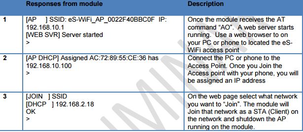
4.4 Access Point
Used to setup the internal Access Point (Network Access). The eS-WiFi runs a Soft Access Point that allows a user to setup a connection to a local network as a STA (Client) on that network or serve up a HTML page to a user.
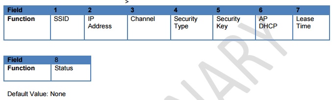
4.4.1 ‘A?’ Show Access Point Settings
Returns Access Point Settings
Usage: A? <CR>
Response from eS-WiFi: >
Es-WiFi,192.168.10.1,1,0,,1,24,0
OK
The following commands are used to setup the Access Point. A typical application will send a sequence of commands to setup the Access point and then have the settings saved in flash memory by using the ‘Z1’ command:
Here is an example of setting up the Access Point information that needs to be saved into Flash upon completion:
AS=0,ABC (Mac address OFF, SSID)
Z6=192.168.10.1 (IP Address)
AC=1 (Channel 1-13 (Japan 14- select country code))
A1=2 (WPA)
A2=Password (Security Key)
AL=24 (Lease Time – Note: AP DHCP is default to ON)
Z1 (Saves setting to flash –USER SAPCE)
If the eS-WiFi module is reset, you can type ‘A?’. All of the settings above have been saved: ABC,192.168.10.1,2,Password,1,24,0
To reset the device to the factory defaults, issue the following three AT commands:
Z3=0 Set Factory User Space
Z2 Erases Flash
ZR Reset
4.4.2 ‘A0’ Activate Access Point
‘A1″ sets the security mode for the Access Point running on the eS-WIFI module.
Usage: A1=<Mode><CR>
Default Value: None
4.4.3 ‘A1’ Set Access Point Security Mode
‘A1″ sets the security mode for the Access Point running on the eS-WIFI module.
Default Value= 0 (Open)
4.4.4 ‘A2’ Set Security Key
The Security Key can be up to 32 characters and is a unique security keyword for access to a wireless network. A system (PC, Smartphone, Tablet, etc.) must use the Security Key to associate with the eS-WiFi Access Point to communicate with the eS-WiFi Module.
Usage: A2=<Key><CR>
Default Value: None
4.4.5 ‘AA’ Get AP DHCP Cached Address(es)
Gets the MAC and IP addresses in the AP DHCP cache
Usage: AA=<Channel><CR>
Default Value: None
4.4.6 ‘AC’ Set Access Point Channel
Sets the channel the Access Point will broadcast on. The channels for 2.4 GHz are from 1 to 13 based upon the Country Code setting and for 5 GHz the channels are 36, 40, 44, 48 and 149, 153, 157, 161 and 165. A setting of 0 selects the auto-channel algorithm for 2.4 GHz.
Usage: AC=<Channel><CR>
Default Value: C2.5.0.X=0, C3.5.2.X=0
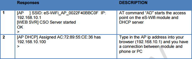
4.4.7 ‘AD’ Activate Access Point Direct Connect Mode
Starts the Access Point, DHCP Server, and minimal CSO (Connection Support Only) Web Server.
The CSO Web Server handles the support for connecting Apple devices with iOS6 and other devices
that require addition support to connect to a captive network.
Usage: AD<CR>
Default Value: None
This mode is used to establish an IPV4 “Direct Connection” to a PC, Smartphone or IOT appliance. Once a PC, smart phone or IOT device joins the eS-WiFi module, the eS-module will issue an IP Address and create a wireless network connection between the module and the Smartphone or IOT appliance. The “Direct Connection” is an Infrastructure connection that has advantages over Adhoc. For example Android does not support Adhoc natively.
Once you have established this infrastructure connection you can setup a Peer-to-Peer connection using UDP, UDP Lite or TCP.
4.4.8 ‘AE’ Exit Access Point Direct Connect Mode
Shuts down the Access Point, DHCP Server, and Web Server when the connected using the Direct Connect mode. This is used for both the ‘A0’ and ‘AD’ commands. For the ‘A0’ command this is only needed when a Direct Connection has been made through the Network Access Web Page.
Usage: AE<CR>
Default Value: None
It is important to create and tear down networks properly. You should shut down the UDP, UDP Lite or TCP prior to issuing the AE command.
4.4.9 ‘AL’ Set Access Point DHCP Lease Time
Set the lease time given by the DHCP Server when an IP address has been assigned.
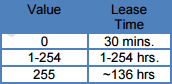
Default Value: 0 (30 mins.)
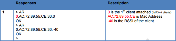
4.4.10 ‘AR’ Get Client RSSI (SoftAP Only, Direct Connect Mode)
Gets the Client RSSI values for all clients connected to the SoftAP in direct connect mode.
i.e. ‘A0’ then select “Direct Connect” from the Configuration page or ‘AD’
Usage: AR<CR>
Default Value: None
Please note that it may take more than one issuance of the command to return a non-zero value.
4.4.11 ‘AS’ Set Access Point SSID
Sets the Access Point SSID. It can be up to 32 characters in total length (including MAC if enabled).
Usage: AS=,<MAC Mode>, <SSID><CR>
 .
.
Default Value: MAC Mode = 1, SSID = eS-WiFi_AP
4.4.12 ‘AT’ Set Maximum Number of AP Clients
Sets the maximum number of AP client that will give an IP address. Please note the AP
itself is considered one of the clients so the total of client equals 5.
Usage: AT=<Number of Clients><CR>

Default Value: 4
4.5 Select Communication Interface
Firmware loaded on the module determines the Host interface. UART or SPIs interfaces are supported for communication with the eS-WiFi module. A separate firmware is needed for each interface.
4.5.1 ‘B?’ Show Communication Interface Settings
Return current Communication Interface settings.
Usage: B?<CR>
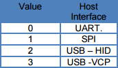

Default Value: None
Response from eS-WiFi in UART Mode: >
0
OK
>
4.5.2 ‘B2’ Set SPI Mode
Set the SPI mode for phase and polarity
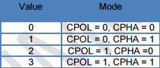
Default: 0
4.5.3 ‘B3’ Set SPI Ready Pin
Set the WKUP pin is has the SDRDY signal for design that didn’t implement the SDRDY pin.
Usage: B3=<value><CR>

Default: 0
4.6 Configure Network Settings
Used to set up the network parameters needed to access a Wi-Fi network. The eS-WiFi can connect to a network using three techniques depending upon your application:
- Your microcontroller can issue a series of AT commands starting with “C1” as outlined in this section
- You can setup a “Direct Connection” a private network as detailed in section above.
- You can start the Access Point and a web server running on the eS-WiFi module and the user will be able to connect to the Web Site, select the SSID and enter the password.
4.6.1 ‘C0’ Join a Network
Using the user defined parameters of SSID, Password, Security Type, etc. attempt to join a WiFi network for access. A successful Join, returns SSID and IP Address; otherwise, an error message is returned. A network cannot be re-joined once the eS-WiFi module has joined a network without first closing the current network connection.
Usage: C0<CR>
Default Value: None


4.6.2 ‘C1’ Set Network SSID
Network Service Set Identifier (SSID) can be up to 32 characters and is a unique identifier (network name) for a wireless network. The eS-WiFi module must use the SSID, Passphrase and WiFi Security to communicate with a wireless network. The SSID is normally supplied by a network administrator.
Usage: C1=<SSID><CR>
4.6.3 ‘C2’ Set Network Passphrase
Network Passphrase can be up to 32 (63/64 for WPA2, C2.4.0 or greater) characters and is a unique security keyword for access to a wireless network. The eS-WiFi module must use the Passphrase associated with the network SSID and the WiFi Network Security to communicate with a wireless network. The Passphrase is normally supplied by a network administrator.
Usage: C2=<Passphrase><CR>
Default Value: C2=NONE
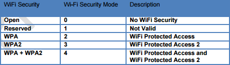
4.6.4 ‘C3’ Set Network Security Type
Select the WiFi Network Security to use for communication with a WiFi network. Below is a list of WiFi Security Modes. The eS-WiFi module must use one of the WiFi Security modes with the associated SSID and Passphrase to communicate with a wireless network. The WiFi Security is normally supplied by a network administrator. The Network WiFi Security Modes are listed in Table 4.2.
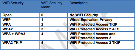
Table 4.2: Network WiFi Security Modes
Usage: C3=<WiFi Security Modes><CR>
Default Value: C3=0
4.6.5 ‘C4’ Set Network DHCP
Dynamic Host Configuration Protocol (DHCP) is used to query a network for an available IP Address that would be used for communications on the network. The eS-WiFi module can use DHCP or a user defined IP Address. The eS-WiFi module must have an IP Address to communicate with a wireless network. The Network DHCP Modes are listed in Table 4.3.
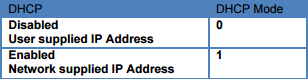
Table 4.3: Network DHCP Modes
Usage: C4=<DHCP Modes><CR>
Default Value: C4=1
The following commands are used to configure the eS-WiFi to join a wireless network. Here is an example of the AT commands:
C1=Inventek (SSID)
C2=Password (Router Passphrase)
C3=2 (WPA)
C4=1 (DHCP)
C0 (eS-WiFi joins the network)
CC=1 (Auto Connect On- Automatically connects on power up)
Z1 (Saves setting to flash)
In the above scenario, as soon as power is applied to the eS-WiFi the module will automatically connect to the Inventek router with the password and settings that are entered. If you want to change to another network, simply make the changes to the AT command and save the new settings into flash using the “Z1” command.
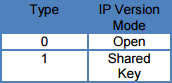
4.6.6 ‘C5’ Set Network IP Version
Set Network IP Version is used to select between Internet Protocol Version 4 (IPV4) and Internet Protocol Version 6 (IPV6). The IP Version must be set for correct operation of the eS-WiFi module on a wireless network. The Network IP Version settings are listed in Table 4.4.
Table 4.4: Network IP Version Modes
Usage: C5=<IP Version Modes><CR>
Default Value C5=0
4.6.7 ‘C6’ Set Network IP Address
Set Network IP Address allows the user to define the IP Address that the eS-WiFi module will use on a wireless network. If DHCP is disabled, the IP Address must be set to allow the eS-WiFi module to work correctly on a wireless network. The IP Address must be entered in dotted-decimal notation, which is defined as xxx.xxx.xxx.xxx for the network address.
If DHCP is enabled, the IP Address will be set by the wireless network on a network join.
Usage: C6=<xxx.xxx.xxx.xxx.><CR>
Default Value: 000.000.000.000
4.6.8 ‘C7’ Set Network IP Mask
Set Network IP Mask is a user defined value for the network net mask (subnetting of the network) used on the WiFi Network. If DHCP is disabled, the net mask must be set to allow the eS-WiFi module to work correctly on a wireless network. The net mask must be entered in dotted-decimal notation, which is defined as xxx.xxx.xxx.xxx.
If DHCP is enabled, the Net Mask will be set by the wireless network on a network join.
Usage: C7=<xxx.xxx.xxx.xxx><CR>
Default Value: 000.000.000.000
4.6.9 ‘C8’ Set Network Gateway
Set Network Gateway is a user defined Gateway IP Address used by the devices on the network to access other networks or as a default gateway when no other IP Address matches any other routes in the network routing table. The Gateway IP Address must be entered in dotted-decimal notation, which is defined as xxx.xxx.xxx.xxx.
Usage: C8=<xxx.xxx.xxx.xxx.><CR>
Default Value: 255.255.255.255
4.6.10 ‘C9’ Set Network Primary DNS
Set Network Gateway is a user defined Gateway IP Address used by the devices on the network to access other networks or as a default gateway when no other IP Address matches any other routes in the network routing table. The Gateway IP Address must be entered in dotted-decimal notation, which is defined as xxx.xxx.xxx.xxx.
Usage: C8=<xxx.xxx.xxx.xxx><CR>
Default Value: 255.255.255.255
4.6.11 ‘CA’ Set Network Secondary DNS
Set Network Secondary DNS is used as a back up to the Primary DNS. The Secondary DNS must be entered in dotted-decimal notation, which is defined as xxx.xxx.xxx.xxx.
Usage: CA=<xxx.xxx.xxx.xxx><CR>
Default Value: 255.255.255.255
4.6.12 ‘CB’ Set Network Join Retry Count
Set Network Join Retry Count is a user defined value that controls the number of times the eS-WiFi module will attempt to join a wireless network before stopping with a failure notice if the system is unable to join the network.
Input range for Join Retries is 0 to 10.
Usage: CB=<Join Retries><CR>
Default Value: 5
4.6.13 ‘CC’ Network Auto Connect
Network Auto Connect allows the user to define weather or not the eS-WiFi module will attempt to join a wireless network after the system is powered up and operational, or after a reset. The Network Auto Connect modes are listed in Table 4.5. You must save the “CC” AT command with the Z1 command to save the setting.
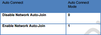
Table 4.5: Network Auto Connect Modes
Usage: CC=<Auto Connect Modes><CR>
Default Value: 0
4.6.14 ‘CD’ Disconnect from Network
To disconnect the eS-WiFi module from a wireless network, the AT Command ‘CD’ is used. ‘CD’ will shut down the network communications and clear the network IP Address, Net Mask, and Gateway Address assigned to the eS-WiFi Module.
Usage: CD<CR>
Default Value: None
4.6.15 ‘CE’ Set Authorization Type
Set the authorization type for WEP security.
Usage: CE=<Type><CR>
Default Value: 0 (Open)
4.6.16 ‘CJ’ Join/Leave IGMP Group
Join or leave a IGMP group.
Usage: CJ=<Action><Group IP Address><CR>,

4.6.17 ‘CN’ Sets or Gets the Country Code
Set the country code for the eS-WiFi module. The country code is a two letter code representing a country which selects which channels are valid to use.
Usage: CN=<Code><CR>
CN<CR>=Gets Country Code
Please see Appendix A for the list of Country Code supported.
Default Value: ‘US’
4.6.18 ‘CR’ Get RSSI of Associated Access Point
Get the RSSI on the currently associated Access Point.
Usage: CR<CR>
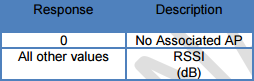
Default Value: None
4.6.19 ‘CS’ Connection Status
Gets the current wireless network connection status.
Usage: CS<CR>
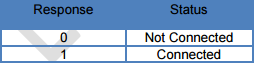
Default Value: None
4.6.20 ‘CV’ Get connected rate.
Usage: CV<CR> The returned number is the bit rate of the current connection (Note: This is not equivalent to the throughput capability.)
4.6.21 ‘CT’ Set WPS Push Button
Sets the GPIO pin to be the PBC (Push Button Configuration) for WPS (Wi-Fi Protected Setup)
Usage: CT=#<CR> Clear setting
CT=!<CR> Status
CT=?<CR> Info
CT=<pin>,<mode> pin = 0-9 (GPIO0-4, ADC0-4), mode = 0=Push, 1-Set Status
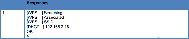
4.6.22 ‘CW’ Connect using WPS Pin or PBC
Connects to an access point using WPS (WiFi Protected Setup) Pin or PBC (Push Button Configuration) methods. Once connected the SSID, Password/Security Key, Security Type settings will be populated and then can be saved using the “Z1” command for use later. Please note when using the Pin method the pin must be set using the “Z7” command.
Usage: CW=<value><CR>

4.6.23 ‘C?’ Show Network Settings
Return current Configured Network Settings.
Usage: C?<CR>
4.7 DNS Commands
4.7.1 ‘D0’ DNS Lookup
This command performs a DNS lookup of a Domain Name to get its IPv4 address. The Domain Name is limited to 64 characters.
Usage: D0=<Domain Name><CR>

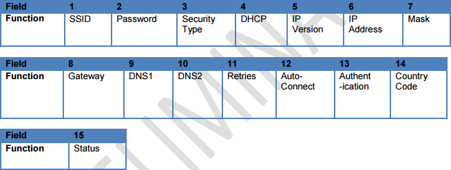
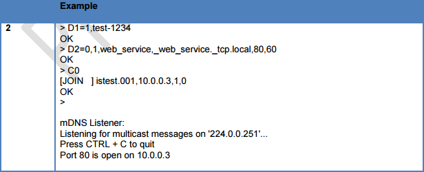
4.7.2 ‘D1’ Set mDNS State and Name
This command Enables/Disables the use of mDNS and sets the Device name. This is supported in C2.4.0 or higher.
Usage: D1=<0/1>,<Device Name><CR>

4.7.3 ‘D2’ Set mDNS Services
This command sets up the two available services. The status will be displayed as part of the Join message (2). This is supported in C2.4.0 or higher.
Usage: D2=<Service # 0/1>,<Instance(32chars)>,<Service(32Chars)>,<Port>,<TTL>
Default: None

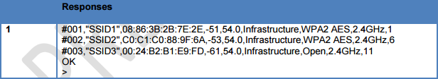
4.8 Scan for Network Access Points
The eS-WiFi module can scan for available networks and return detailed information about networks found without having to join a network. The information returned on the available networks includes SSID, BSSID, RSSI, Data Rate, Network Type, Security, Radio Band, and Channel. The information returned about Network Access Points can be used in joining one of the networks.
Scanning for Network Access Points is a very handy command for determining what wireless networks are in listening range of the eS-WiFi module.
4.8.1 ‘F0’ Scan for Network Access Points
Find Networks can be used to scan for available networks and return information about the networks found.
Usage: F0<CR>
4.8.2 ‘F1’ Set Scan Repeat Count
Set Repeat Count is a user defined value that controls the number of times to scan for Network Access Points.
Input range for Set Scan Repeat Count is 0 to 255.
Usage: F1=<Set Scan Repeat Count><CR>
Default Value: 0
4.8.3 ‘F2’ Set Scan Delay
Set Scan Delay is a user defined value that sets the amount of time in milliseconds to wait between scans for Network Access Points.
Input range for Set Scan Delay is 0 to 5000, which represents the delay in milliseconds.
Usage: F2=<Set Scan Delay><CR>
Default Value: 1000
4.8.4 ‘F3’ Set Scan Channel
Set Scan Channel to scan for.
Input range 0=None 1 to 14
Usage: F3=<Channel><CR>
Default Value: 1
4.8.5 ‘F4’ Set Scan BSSID
Set Scan Channel BBSID to scan for.
Usage: F4=<XX.XX.XX.XX.XX.XX><CR>
Default Value: None
4.8.6 ‘F5’ Set Scan SSID
Set Scan Channel SSID to scan for.
Input range #=Clear, <32 characters SSID>
Usage: F5=<32 character SSDI><CR>
Default Value: None
4.8.7 ‘F?’ Show Scan Settings
Returns current Scan Settings.
Usage: F?<CR>

Default Value: None
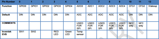
4.10 GPIO / ADC Information
The GPIO’s on the module can be configured to control LEDs, read buttons and digital inputs or outputs, etc. The output is a 3.3V CMOS level. On the evaluation board (EVB), there are switches and LED’s that can be controlled as shown in the table below. The process is to configure the pins as required with the AT command ‘G4’ and then to read and write as required.
A couple of examples:
1. Issue an AT command to see if you are connected to the network. Once you know you are connected you can light an LED.
2. Setup GPIO2 as an A/D, connect a temperature sensor and read the value.
A user can setup and read the state of GPIO’s 1-7 with the AT command. Some firmware revisions may use some of the GPIO’s for special functions. For example, the SPI firmware uses the GPIO2 (ADC) for the SPI ready function.
4.10.1 ‘G2’ Read GPIO/ADC
Reads the current value of the specified GPIO or ACD pin
Usage: G2=<Pin Number>,<Value><CR>

Default Value: None
1. G4=0,2 This configures GPIO0 as button with de-bounce features enabled
2. G2=0,2 = This function reads GPIO and reports the value
4.10.2 ‘G3’ Write GPIO
Writes the current value of the specified GPIO pin.
Usage: G3=<Pin Number>,<Type Value>,<Value><CR>
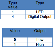
Default Value: None
4.10.3 ‘G4’ GPIO Setup
Sets the type of the specified GPIO pin.
Usage: G4=<Pin Number>,<Value><CR>
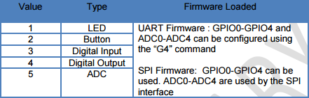
Default Value: None
4.10.4 ‘GT’ Get UTC Time
Gets the UTC time from the internet (Item 1 below). If not connected to the internet, it will give the number of milliseconds since power-up. (Item 2 below)
Usage: GT<CR>
4.10.5 ‘G?’ Show GPIO Settings
The AT Command ‘G?’ will return the GPIO pin type. To confirm your settings and the sequence of returned states from this request will be grouped by type, not by pin number.
Usage: G?<CR>
Default Value: As shown above
4.11 Software Information
Information about the AT Command application that includes Firmware Version, WICEDTM Version, IP Stack Version, RTOS Version and configuration can be accessed using the following AT Commands.
4.11.1 ‘IC’ Is Endpoint Configured
The AT Command ‘IC’ will return is an endpoint has been configured by the CloudBourne Application.
Usage: IC=<unique portion of the endpoint, up to 64 characters><CR>
Default Value: None
4.11.2 ‘I?’ Show Applications Information
The AT Command ‘I?’ will return Application, Firmware, Platform, IP Stack, and RTOS information.
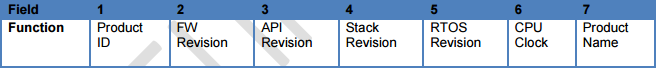
Default Value: None
4.12 Miscellaneous Command
4.12.1 ‘MF’ Test External Serial Flash
Does an erase, write, read, and verify test on the external serial flash used for Factory Reset or Over-The-Air (OTA) firmware updates.
Usage: MF<CR>

Default Value: None
4.12.2 ‘MJ’ Manufacturing Test
The MJ command does an AP Connect, checks RSSI, and pings the gateway address. The default RSSI limit is -90. The default SSID is set to ism_mfg_test, security is set to open, and the password is none.
Usage: MJ<CR>
MJ=<RSSI Limit><CR> MJ=-70<CR>
4.12.2 ‘MR’ Message Read (SPI Only)
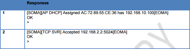
This command reads any asynchronous message that occurs based on an asynchronous event such as a device connecting to the Soft AP(Access Point) using A0 and AD commands or a TCP connection message from the P5 command. The message will have a Start Of Message Asynchronous [SOMA] and End Of Message Asynchronous [EOMA] delimiters.
4.12.4 ‘MS’ Suppress Async Message DHCP
Suppresses the DHCP assigned messages from being sent to the host.
Usage: MS=<Disable/Supress><CR>
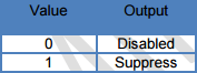
Default Value: 0
4.12.5 ‘MT’ Set Message Type
Set the message type. Normal: full messages including usage on error or Simple: No usage on error.
Usage: MS=<Disable/Simple><CR>

Default Value: 0

4.13 Transport Communication
Transmission Control Protocol (TCP) and User Datagram Protocol (UDP) are used for point-to-point or port-to-port communications on a network. TCP is a guaranteed port-to-port communication protocol that is used to insure data is transferred error free between a server and client. UDP is considerd to be faster than TCP for the movement of data over a network; however, UDP does not guarantee the delivery of data between a server and a client. UDP lite is UDP with the partial removal of checksums which may improve network data movement performance but may be more prone to data errors.
The eS-WiFi module supports TCP, UDP, and UDP lite for port-to-port communication.
The eS-WiFi module can be configured as a server or client on a network for TCP/UDP communication. In Transport server mode, the eS-WiFi module will wait in the background for connection requests. Once a network device requests a connection to the server, the server will enter a mode were data can be requested by a client and data delivered to a client.
The eS-WiFi module can also be configured as a client for TCP/UDP communications to make requests to a Transport server on the wireless network.
If UDP or UDP lite is used, it is recommended that the user develop their own packet numbering and error checking for data transfers.
4.13.1 ‘P0’ Set/Display Communication Socket
Set/Display the communication socket for TCP, UDP, or UDP Lite communications. All the Px commands for communications are duplicated for each socket. The Rx and Sx are tied to the communication socket selected by ‘P0’.
Usage Set: P0=<Communication Socket 0 to 3><CR>
Usage Display: P0<CR>

Example: P0=1<CR> //Set Socket 1
P1=0<CR> //TCP
P3=192.168.2.2<CR> //Remote Host
P4=8002<CR> //Remote Port
P6=1<CR> //Start Client connection
S3=4<CR>1234 //Send Data
R0<CR> //Receive Data
P0=2<CR> //Set Socket 2
P1=0<CR> //TCP
P3=192.168.2.3<CR> //Remote Host
P4=8002<CR> //Remote Port
P6=1<CR> //Start Client connection
S3=4<CR>4321 //Send Data
R0<CR> //Receive Data
P0=1<CR> //Set Socket 1
4.13.2 ‘P1’ Set Transport Protocol
Set Transport Protocol allows the user to enable selection of ether TCP, UDP, UDP Lite, TCP-SSL for network port-to-port communications. For Firmware Version C3.5.2.X or greater, MQTT is available and is selected with this command. The Transport Protocols modes are listed in Table 4.6.
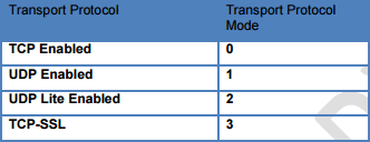
Table 4.6: Transport Protocol Modes
Usage: P1=<Transport Protocol Modes><CR>
Default Value: P1=0
4.13.3 ‘P2’ Set Transport Local Port Number
Set Transport Local Port Number allows the user to define the local port that the eS-WiFi module will listen on for Transport communication connections.
Input range for Transport Local Port Number is 0 to 65535.
Usage: P2=<Transport Local Port Number><CR>
Default Value: P2=5024
Refer to documentation on TCP/UDP communications for pre-defined port information.
4.13.4 ‘P3’ Set Transport Remote Host Port IP Address
Set Transport Remote Host IP Address is a user defined address that the eS-WiFi module will use to contact a Transport server on the network. The Transport Remote Host IP Address must be entered in dotted-decimal notation, which is defined as xxx.xxx.xxx.xxx for the network address.
Usage: P3=<xxx.xxx.xxx.xxx><CR>
Default Value: 000.000.000.000
4.13.5 ‘P4’ Set Transport Remote Port Number
Set Transport Remote Port Number allows the user to define the port number for a Transport Server on the network that the eS-WiFi module will use for communications with that server.
Input range for Local Port is 0 to 65535.
Usage: P4=<Local Port><CR>
Default Value: P4=5025
4.13.6 ‘P5’ Stop/Start Transport Server
Stop/Start Transport Server is used to stop or start the eS-WiFi module’s Transport Server mode. The AT Command ‘P1’ is used to select between TCP, UDP or UDP Lite server protocols. The Transport Server modes are listed in Table 4.7.
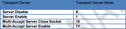
Figure 4.7: Transport Server Modes
Usage: P5=<Transport Server Modes><CR>
Default Value: P5=0
4.13.7 ‘P6’ Stop/Start Transport Client
Stop/Start Transport Client is used to stop or start the eS-WiFi module’s Transport Client mode. The AT Command ‘P1’ is used to select between TCP, UDP or UDP Lite server protocols. The Transport Server modes are listed in Table 4.8.
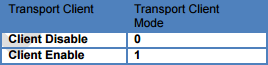
Figure 4.8: Transport Server Mode
Usage: P6=<Transport Client Modes><CR>
Default Value: P6=0
4.13.8 ‘P7’ Start/Stop Request TCP Loop
Controls the Request TCP Loop. Closing socket allows the next listen backlog to be handled.
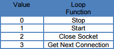
Default Value: P7=0
4.13.9 ‘P8’ Set Listen Backlogs
Set the number of listen backlogs (TCP connection requests) that can be queued.
Usage: P8=<value><CR>
Range: 1 to 6 backlogs
Default Value: P8=1
4.13.10 ‘P9’ SSL Certification Verification Level
This command sets the verification level for the server/client certificate
Usage: P9=<Level><CR>
Level: 0 = None, 1 = Optional(Root CA only), 2 = Required(Root CA/Certificate/KEY)
4.13.11 ‘PA’ Set Custom Certificate Authority
Set a custom certificate authority name for simple verification of the SSL certificate
Usage: PA=<index0/1><Custom CA, 63 characters max><CR>
Default Value: None
4.13.12 ‘PB’ Set Root CA Verification Results
Set the TCP API message timeout to the stack.
Default Value: 0
4.13.13 ‘PC’ Write Security Certificates
Writes a security certificates to flash.
Usage: PC=<Certificate 0/1>,<Number of Bytes>\r<Byte of certificate><CR>
Default Value: None
4.13.14 ‘PD’ Write Security Key
Writes a security keys to flash.
Usage: PD=<Key 0/1>,<Number of Bytes>\r<Byte of key><CR>
Default Value: None
Writes a security keys to flash.
Usage: PD=<Key 0/1>,<Number of Bytes>\r<Byte of key><CR>
Default Value: None
4.13.15 ‘PE’ Certificate Set Availability
Usage: PE\r
output: <Set 0, 0-used/1-available>,<Set 1, 0-used/1-available>,<Set 2, 0-used/1-available>
Note: Used will be reported if any one feature of the set is used.
format: PE=<certificate set 0/1/2>\r
output: <CA, 0-used/1-available>,<Cert, 0-used/1-available>,<Key, 0-used/1-available>
4.13.16 ‘PF’ Set Active Certificate
Usage: PF= <function>,<Certificate set>\r
Function: 0= TLS, 1= AWS
Certificate” 0-2
Default Value: TLS=0, AWS=2
4.13.17 ‘PG’ Program CA, Certificate or key
Format: PG=<certificate>,<Type>,<Len>\r <data bytes>
Certificate Set: 0-2
Type: 0=CA, 1=Certificate, 2= Key
Len: Length of CA, Certificate, or Key in bytes
Data Bytes CA, Certificate, or Key bytes
Note for C3.5.2.1.BETA4 or above:
If you write the same CA, Certificate, or Key to the same location that the same
CA, Certificate, or Key was written prior it will perform a verify.
Output: Match or an error.
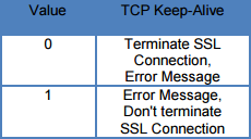
4.13.18 ‘PK’ TCP Keep-Alive
Enables/Disables and sets the TCP Keep-Alive Time-to-Idle. This is useful in detecting broken TCP connections. If enabled and a TCP connection is broken, the S0/S3 commands will respond with a
-1 once the broken connection is detected.
Usage: PK=<value1>,<value2><CR>

Value2 Range: 250ms to 7200000ms (default is 7200000ms)
4.13.19 ‘PM’ MQTT Attributes
format: PM\r
output: <publish topic>,<subscribe topic 0>,<subscribe topic 1>,<subscribe topic 2>,<MQTT mode>,<user name>,<password>,<client id>,<keepalive>
Note: if not set the field will be blank (i.e., nothing between commas)
PM=0 – Set Publish Topic
format: PM=0,<publish topic>\r
publish topic: 64 alphanumeric characters
PM=1 – Set Subscribe Topic
format: PM=1,<subscribe topic>\r
subscribe topic: 64 alphanumeric characters
Note: Only set index 0
PM=1,<index>,<subscribe topic>\r
index: 0-2, 0 same as original format above
subscribe topic: 64 alphanumeric characters
PM=2 – Set MQTT Security Mode
format: PM=2,<security mode>\r
security mode: 0=None 1=User Name/Password, 2=CA/Cert/Key
PM=3 – Set User Name
format: PM=3,<user name>\r
user name: 32 alphanumeric characters
PM=4 – Set User Name
format: PM=4,<password>\r
password: 32 alphanumeric characters
PM=5 – Set MQTT Client ID
format: PM=5,<client id>\r
client_id 24 alphanumeric characters
PM=6 – Set MQTT Keep Alive
format: PM=6,<keepalive>\r
keepalive 0-65535 seconds
PM command Clear Attribute
format: PM=<command>,”\r
command: 0,1,3,4,5,6
format: PM=<command>,<index>,”\r
command: 1 (when using multiple subscribe topics)
4.13.20 ‘PY’ Set TCP API Message Timeout
Set the TCP API message timeout to the stack.
Usage: PY=<Timeout in ms><CR>
Range: #=Restore Default, 0-65535, ?-Info
Default Value: 10000
4.13.21 ‘PX’ Set TCP Streaming Mode
Set the TCP to automatically stream data as a Client or a server.
Usage: PX=0{0=Server Mode;1=Client Mode},GPIO
Examples
Usage: PX=<1,0><CR> (Client Mode with GPIO 0 as escape) or
Usage: PX=<0,0><CR> (Server Mode with GPIO 0 as the escape)
Streaming Mode allows raw, un-formatted data to be sent to and from the module over Wi-Fi via the serial port. Data shows up on the UART and automatically streams wirelessly as either a client or a server. Perform the initial AT command setup to define the mode and anything that shows up on the UART is automatically sent.
Here is a simple Client setup procedure:
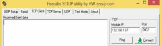
Plug the eS-Wifi module into the PC and start a terminal program (e.g. Teraterm) and set default baud rate to 115,200 to communicate with the module. Also, open Hercules as a server connected to the same network.
- Join the eS-WiFi module to a network using AT commands
- C1= SSID \r
- C2= Password \r
- C3= 0 \r
- C0 \r
- P0=0\r
- P3=192.168.1.xx\r
- P4=8002
- S1=7
- S2=1000
- PX= 1,0
“Client must initiate first”
Type away and data streams anything that shows up on the UART.
Server Setup: Add the following command for Server Mode:
P2=8002 LOCAL PORT
PX=0,0 Server Mode PX=0{0=Server Mode;1=Client Mode},GPIO
4.13.22 ‘P?’ Show Transport Settings
Return current Transport Communication Settings.
Usage: P?<CR>


Default Value: None
4.14 Receive Transport Data
Once the Transport Protocol has been defined and either the server or client mode has been enabled, data can be received from a connected server or client using the AT Command ‘R0’ with AT Command ‘R1’ setting the size of data to read from the transport protocol stack. For TCP data, multiple reads may be needed to return all of the available data; however, for UDP, data received greater than the number of bytes defined by the AT Command ‘R1’ will be lost.
4.14.1 ‘R0’ Read Transport Data
Available receive data is read using the AT Command ‘R0’. ‘R0’ reads the transport buffer for AT Command ‘R1’ size bytes. Multiple reads may be needed to read all of the available TCP data. UDP data received greater than the bytes size defined by R1 will be lost.
Usage: R0<CR>
Default Value: None


4.14.2 ‘R1’ Set Read Transport Packet Size (bytes)
The AT Command ‘R1’ is a user defined value for the packet size of data to return a data returned. The AT Command ‘R1’ should be set before performing AT Command ‘R0’. The input range for AT Command ‘R1’ is 0 to 1460 bytes.
Usage: R1=<Data Package Size><CR>
Default Value: R1=1460
4.14.3 ‘R2’ Set Read Transport Timeout (ms)
The AT Command ‘R2’ is a user defined value for the amount of time in milliseconds to wait on the Read Transport Data AT Command ‘R2’ to finish. The input range for R2 is 0 to 30000 milliseconds.
Usage: R2=<Read Transport Timeout><CR>
Default Value: R1=5000
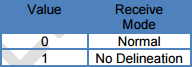
4.14.4 ‘R3’ Set Receive Mode
The AT Command R3 sets the receive mode. In receive mode = 1 the CRLF(Carriage Return/ Line Feed)
delineation are removed from the Read response.
Default Value: None
4.14.5 ‘R?’ Show Read Transport Settings
Return current Receive Transport Data Settings.
Usage: R?<CR>

Default Value: None
4.15 Write Transport Data
Once the Transport Protocol has been defined and either the server or client mode has been enabled, data can be written to a connected Transport Server or Client using the AT Command ‘S0’ with AT Command ‘S1’ defining the size of data to write.
4.15.1 ‘S0’ Write Transport Data
The AT Command ‘S0’ is used to write data to a Transport Server or Client. The size of the data to write is defined via the AT Command ‘S1’. After the AT Command ‘S0’ is entered, any data writing to the eS-WiFi module’s selected communicating interface will be sent to a connected Transport Server or Client. Once the number bytes defined by AT Command ‘S1’ have been sent, the eS-WiFi module will return back to the AT Command mode waiting for the next ‘AT Command’. If more bytes are written to the eS-WiFi module than are defined by the AT Command ‘S1’, the data will be lost and error message will be returned on the excess data written to the eS-WiFi module selected communication interface.
Usage: S0<CR><Data>
4.15.2 ‘S1’ Set Write Transport Packet Size (bytes)
AT Command ‘S1’ is used to define the packet size of data to write to a connected Transport Server or Client. The AT Command ‘S1’ should be set before a performing AT Command ‘S0’. We recommend you use the S3 function for most applications since it combines the ‘S0’ and ‘S1’ commands.
Usage: S1=<Data Packet Size><CR>
Default Value: S1=1460
4.15.3 ‘S2’ Set Write Transport Timeout (ms)
The AT Command ‘S2’ is a user defined value for the amount of time in milliseconds to wait on the Write Transport Data AT Command ‘R2’ to finish. The input range for S2 is 0 to 30000 milliseconds.
Usage: S2=<Write Transport Timeout><CR>
Default Value: S1=5000
4.15.4 ‘S3’ Write Transport Data
The AT Command ‘S3’ is used to write data to a Transport Server or Client. The size of the data to write is defined by the first parameter. After the AT Command ‘S3’ is entered (i.e. the <CR> is received by the eS-WiFi module, any data writing to the eS-WiFi module’s selected communicating interface will be sent to a connected Transport Server or Client. Once the number bytes defined by the first parameter have been sent, the eS-WiFi module will return back to the AT Command mode waiting for the next ‘AT Command’. If more bytes are written to the eS-WiFi module than are defined by first parameter, the data will be lost and error message will be returned on the excess data written to the eS-WiFi module selected communication interface.
Usage: S3=<Data Packet Size<CR><Data>
4.15.5 ‘SF’ SPI Flash CS Pin
The AT Command ‘SF’ is used to set the CS (Chip Select) pin for the Serial SPI Flash for OTA.
Usage: SF=<pin><CR>
Pin = 0 (SSN pin), 1-5 (GPIO0-4)
Default Value: 0
4.15.5 ‘S?” Show Write Transport Settings
Return current Write Transport Data Settings.
Usage: S?<CR>

Default Value: None
4.16 Ping IP Target Address
Ping is a network utility for testing the reachability of hosts on a network. Ping will measure the round-trip time to a host or return a timeout if the host is not reachable.
4.16.1 ‘T0’ Ping IP Target Address
The AT Command ‘T0’ will Ping a remote host returning the round-trip time or a timeout message. The host IP Address used by Ping must be set up by using the AT Command ‘T1’.
Usage: T0<CR>
Default Value: None
4.16.2 ‘T1’ Set Ping Target Address
The AT Command ‘T1’ is used to set the IP Address of the host to Ping.
Usage T1=<xxx.xxx.xxx.xxx><CR>
Default Value: 000.000.000.000
4.16.3 ‘T2’ Set Ping Repeat Count
The AT Command ‘T2’ is used to define the number of times to repeat a Ping of a host on the network.
Usage T2=<Repeats><CR>
Range: 0-65534, 65535=Continuous
Default Value: T2=0
4.16.4 ‘T3’ Set Ping Delay (ms)
The AT Command ‘T3’ is used to define the amount of time to wait between Pinging a host on the network. The amount of time to wait is defined in milliseconds and is limited to the range of 0 to 5000.
Usage T3=<delay in ms><CR>
Default Value: T3=0
4.16.5 ‘T?’ Show Ping Settings
Return current Ping Settings.
Usage: T?<CR>

Default Value: None
4.17 Configure UART
The eS-WiFi module can be configured to use its serial interface for communications with a host computer or terminal console programs. Currently, the only UART Configuration mode for the eS-WiFi module is the serial interface, which is set to 8 data bits, no parity, one stop bits. The eS-WiFi module can support baud rates from 1200 to 3916800 baud. The AT Command ‘U2’ is used to set the baud rate. The eS-WiFi module interface can also be set up in ASCII or Binary mode for data. In addition, the eS-WiFi module can be configured to generate timeout messages on the serial communications.
4.17.1 ‘U0’ Activate UART Settings
The AT Command ‘U0’ is used to store the current eS-WiFi module UART settings in non-volatile memory for power on or after a reset for automatic configuration of the UART.
Usage: U0<CR>
Default Value: None
4.17.2 ‘U2’ Set UART Baud Rate
The AT Command ‘U2’ is used to set the baud rate for the Comm Port selected using the AT Command ‘U1’. Table 4.10 list the available eS-WiFi module baud rates.
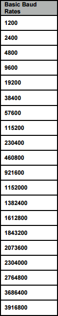
Table 4.10: Basic Baud Rates
Usage: U2=<Baud Rate><CR>
Default Value: U2=115200
4.17.3 ‘U?’ Show UART Setting
Return current UART Configuration.
Usage: U?<CR>

Default Value: None
4.18 WLAN
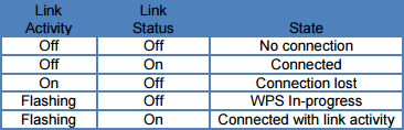
4.18.1 ‘WL’ Set GPIOs for Link Status and Activity
Sets the GPIO pins for WLAN link status and activity. The link status can also be used as an IRQ to the host processor to indicate if the module is connected to a wireless network.
Usage: WL=<Arg1><Activity GPIO, 0-9>,<Polarity 0=Active Low/1=Active High><CR>
Arg1:
- # to clear(reset) GPIO pin to original settings
- ? to show current values
- Link GPIO, 0-9
Examples:
> WL=#
OK
> WL=4,3,1
OK
> WL=?
4,3,1
OK
>
Note: GPIOs 0-4 are GPIO0-4 and GPIOs 5-9 are ADC0-4.
Default Value: Link = 255, Activity=255
4.19 System Information Flash
The AT Commands can be saved into flash to initialize the system, such as customer Mac address, or the auto connect to join a network once the SSID and password have been saved into “User Space”.
The flash memory is architected to have two banks of flash, partitioned as:
- Factory Default Space
- Customer User Space
We recommend that all default settings are saved in “User Space” and if there are any errors encountered with the settings while in operation a switch can be made to the “Factory space” before executing a reset. This will erase the flash in the “User Space”, restart the module in a known state using the default settings in the “Factory Space”.
4.19.1 ‘Z0’ Reset To Factory Defaults
Reset the current user space settings to factory default. The settings are not saved until a ‘Z1’ command is issued. You cannot be connected to a Network when trying to reset eS-WiFi to defaults.
Usage: Z0<CR>
Default Value: None
4.19.2 ‘Z1’ Save Current Settings
Saves the current user setting to the space selected with the ‘Z3’ command.
Usage: Z1<CR>
Default Value: None
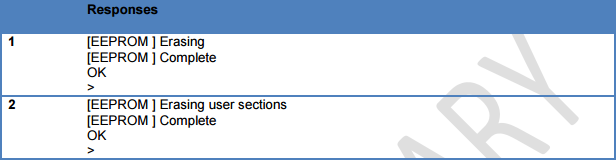
4.19.3 ‘Z2’ Clear Saved Settings
Clears the save settings space based upon the space selected with the ‘Z3’ command.
Usage: Z2<CR>
Default Value: None
4.19.4 ‘Z3’ Set (Select) Factory/User Space
Selects the space that will be used by the ‘Z1’ and ‘Z2’ commands.

Default Value: None
4.19.5 ‘Z4’ Set MAC Address
Sets the MAC address.
Usage: Z4=<XX:XX:XX:XX:XX:XX><CR>
Default Value: None
4.19.6 ‘Z5’ Get MAC Address
Gets the MAC address.
Usage: Z5<CR>
Default Value: None
4.19.7 ‘Z6’ Set Access Point IP Address
Sets the Access Point IP address.
Usage: Z6=<XXX.XXX.XXX.XXX><CR>
Default value: 192.168.10.1
4.19.8 ‘Z7’ Set WPS Pin
Sets the 8 digit numeric WPS (WiFi Protected Setup) pin number.
Usage: Z7=<XXXXXXXX>
Default Value: None
4.19.9 ‘Z8’ Get WPS Pin
Gets the WPS (WiFi Protected Setup) pin number.
Usage: Z8<CR>
Default Value: 12345678
4.19.10 ‘ZC’ Clear Factory Lock Switch
Clears the Factory Lock switch, allowing the factory flash space to be changed.
Usage: ZC=0<CR>
Default Value: None
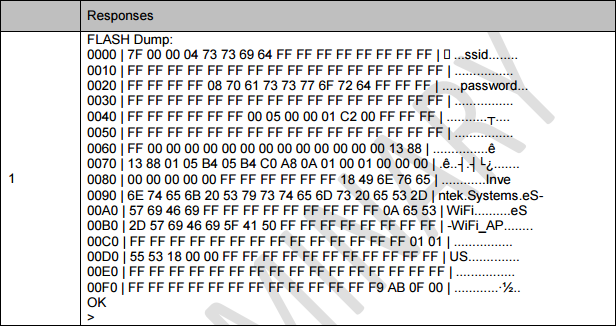
4.19.11 ‘ZD’ Flash Dump
Dumps the selected space from the ‘Z3’ command to the host interface.
Usage: ZD<CR>
Default Vale: None
4.19.12 ‘ZF’ Set Factory Lock Switch
Sets the Factory Lock switch, making the Factory space not unchangable.
Usage: ZF=1<CR>
Default Value: 0 (Unlocked)
4.19.13 ‘ZN’ Set Product Name
Sets the Product Name reported by the Access Point web pages, the ‘I?’ and ‘Z?’ commands. The name can be up to 32 alphanumeric characters long.
Usage: ZN=<Product Name><CR>
Default Value: Inventek Systems eS-WiFi
4.19.14 ‘ZO’ OTA Firmware Update
Get the URL for the update firmware, downloads to external serial flash and then updates the micro-processors on board flash and re-boots.
Usage: Z0=<1 – 128><CR><URL Bytes(http://domain:port/bin_file_path>
Default Value: None
4.19.15 ‘ZP’ Power Management
Enable/Disable Power Management features.
Usage: ZP=<Feature>,<Value><CR>
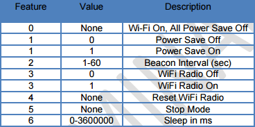
Default Value: Feature 0 (WiFi On, All Power Save Off)
4.19.16 ‘ZR’ Reset Module
Software reset of the module. The equivalent of using the RTSN pin.
Usage: ZR<CR>
Default Value: None
4.19.17 ‘ZS’ Get Serial Number
This command gets the serial number of the module
Usage: ZS<CR>
> ZS
0029001F-33334707-30353834
OK
>
4.19.18 ‘ZT’ Set Serial Number
This command sets the module serial number
Usage: ZT=<serial number>
serial number = 16 characters
> ZT=3333470730353835
OK
4.19.19 ‘ZU’ Firmware Upgrade (M3G and M4G Only, uses STM32F205/405 boot loader)
Starts the STM32F205/405 built in boot loader to upgrade the firmware.
Usage: ZU<CR>
Default Value: None
.
4.19.20 ‘ZV’ Set OTA Method
Selects the method for the OTA download.
Usage: ZV=<Value><CR>

Default Value: None
4.19.21 ‘Z?’ Show System Settings
Returns current system settings.
Usage: Z?<CR>
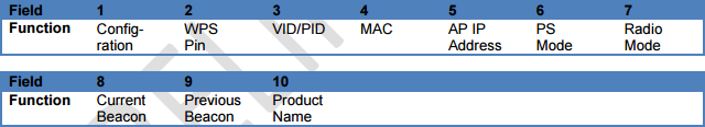
Default Value: None
5 Example eS-WiFi Module AT Command Usage
This section of the eS-WiFi Module User’s Manual covers example usage of the AT Command Set. Areas covered include Changing the Baud Rate, Scanning for Access Points, Joining Networks and transferring data via Transmission Control Protocol using TCP and UDP.
5.1 Entering Human Readable Command Mode
The eS-WiFi Module supports a Human Readable Command Mode for console interaction with the AT-Command set. For the AT Command usage examples that follow, the Human Readable Command Mode will be used. Sending the AT Command ‘$$$’ at the console prompt will put the eS-WiFi Module into human readable mode. Sending the AT Command ‘—‘ will take the eS-WiFi Module out of Human Readable mode and back into Machine Readable Mode, which is the default console mode for the eS-WiFi Module.
Entering Human Readable Mode example:
>$$$
Entering CMD mode —
OK
>
5.2 Changing the Baud Rate
One of the first things that may be useful when using the eS-WiFi Module is to up the data rate of the eS-WiFi Module serial interface for faster interaction with the console and data transfer.
Check Current Baud Rate:
>U?
Communication Port: UART
Baud Rate: 115200
Data Width: 8 bit
Parity: NONE
Stop Bits: 1
Mode: ASCII
RX Timeout: 0 ms
TX Timeout: 0 ms
OK
>
Set New Baud:
>U2=921600
OK
>
Activate Baud Change:
>U0
At this point the eS-WiFi Module will expect a faster or slower baud rate depending on the baud rate used for U2. The next step is to change the baud rate of the system to continue communicating with the eS-WiFI Module. After changing the System baud, sending a <CR> should return the console prompt ‘>’, If not reset the eS-WiFi Module and retry changing the baud.
Check Baud Rate After Change:
>U?
Communication Port: UART
Baud Rate: 921600
Data Width: 8 bit
Parity: NONE
Stop Bits: 1
Mode: ASCII
RX Timeout: 0 ms
TX Timeout: 0 ms
OK
>
Finding Access Points
The first steps in joining a network is determining available Access Points in the listening range of the eS-WiFi Module. The eS-WiFi Module AT Command Set supports functions for finding Access Points. The AT Command for finding Access Points can be used without joining a network.
5.3 Find Access Points:
> F0
Waiting for scan results…
#001 SSID : mars
BSSID : CC:33:CC:99:39:00
RSSI : -39dBm
Max Data Rate : 54.0 Mbits/s
Network Type : Infrastructure
Security : WPA2 AES
Radio Band : 2.4GHz
Channel : 2
#002 SSID : jupiter
BSSID : EE:99:FF:AA:DD:00
RSSI : -90dBm
Max Data Rate : 54.0 Mbits/s
Network Type : Infrastructure
Security : WPA2 AES
Radio Band : 2.4GHz
Channel : 1
#003 SSID : saturn
BSSID : FF:11:00:55:CC:EE
RSSI : -90dBm
Max Data Rate : 54.0 Mbits/s
Network Type : Infrastructure
Security : WEP
Radio Band : 2.4GHz
Channel : 6
#004 SSID : uranus
BSSID : 33:44:99:44:11:CC
RSSI : -94dBm
Max Data Rate : 54.0 Mbits/s
Network Type : Infrastructure
Security : WPA2 AES
Radio Band : 2.4GHz
Channel : 11
End of scan results
OK
>
If needed, the eS-WiFi Module can be set up to scan a number of times for Access Points. This mode can be helpful during set up or debug on a network. The example below sets up the eS-WiFi Module to run 5 Access Point scans.
> F1=5
OK
>
> F0
Waiting for scan results…
… (returned data)
End of scan results
Waiting for scan results…
… (returned data)
End of scan results
Waiting for scan results…
… (returned data)
End of scan results
Waiting for scan results…
… (returned data)
End of scan results
Waiting for scan results…
… (returned data)
End of scan results
OK
>
The eS-WiFi Module can also be set up using an AT Command to delay between scans. The delay is set in milliseconds. The time range for delay is 0 to 5000 milliseconds.
Delay one second between scans:
> F2=1000
OK
>
Check current Find settings:
> F?
Scan Repeats: 10
Scan Delay in ms: 1000
OK
>
5.4 Join Network Access Point
To join a Network Access Point, the SSID, the PASSWORD, the Security Mode, and the IP Address mode (DHCP or locally assigned IP Address) must be set. See your network administrator for information needed to accessing Access Points on your network.
Using the information returned from previous network scan (F0) and network information supplied by the Network Administrator, the eS-WiFi module can be configured to join an Access Point on the Network.
The following example shows how to join an Access Point using DHCP, however, a locally defined IP Address can also be used. Refer to the sections 4.6.4, 4.6.6, and 4.6.7 on setting a local IP Address for the eS-WiFi module.
Set SSID for Access Point:
> C1=mars
Ok
>
Set Password for Access Point:
> C2=PASSWORD
OK
>
Set Security Mode (WPA2 AES) for Access Point:
> C3=3
OK
>
Set eS-WiFi Module IP Address via DHCP:
> C4=1
OK
>
Check Network Join settings before joining Access Point:
> C?
SSID: mars
PSWD: PASSWORD
SECURITY: WPA2 AES
DHCP: Enabled
IP: IPV4
IP ADDR: 0.0.0.0
MASK: 0.0.0.0
GW ADDR: 0.0.0.0
DNS1: 0.0.0.0
DNS2: 0.0.0.0
Join Retries: 5
Auto Connect: 0
Status: Not Connected
OK
>
Join Network Access Point mars, using PASSWORD, WPA2 AES, and DHCP:
> C0
Joining : mars
Successfully joined : mars
Obtaining IP address via DHCP
Network ready IP: 192.168.1.117
OK
>
Check Network Join Settings after joining Access Point:
> C?
SSID: mars
PSWD: PASSWORD
SECURITY: WPA2 AES
DHCP: Enabled
IP: IPV4
IP ADDR: 192.168.1.117
MASK: 255.255.255.0
GW ADDR: 192.168.1.1
DNS1: 0.0.0.0
DNS2: 0.0.0.0
Join Retries: 5
Auto Connect: 0
Status: Connected
OK
>
Turn on auto connect
“CC”
Save settings in Flash above:
“Z1”
5.5 Ping a System on a Network
From time to time there is a need to Ping a system on a network or Ping a system while debugging a connection on the network. The eS-WiFi module can be configured to Ping systems on a network. To Ping a system on a network from the eS-WiFi Module, the IP Address of the system must be set up. In addition to setting up IP Address for the system to ping, the number of times to perform the Ping and the delay between Pings can be set. Assuming that eS-Wifi Module has already joined to a network, the following steps will ping a system on the network.
Set Ping IP Address to 192.168.1.90 for a system on the Network:
> T1=192.168.1.90
OK
>
Set Ping Repeats to 5:
> T2=5
OK
>
Set Ping Delay to 500 milliseconds:
> T3=500
OK
>
Check Ping Settings:
> T?
Ping Target Address: 192.168.1.90
Ping Repeats: 5
Ping Delay: 500 ms
OK
>
Ping 192.168.1.90 on the network for five times with a 500 millisecond delay between pings:
> T0
Pinging: 192.168.1.90
Ping Reply 32ms
Pinging: 192.168.1.90
Ping Reply 5ms
Pinging: 192.168.1.90
Ping Reply
5.6 Transmission Control Protocol
To move data across a network, Transmission Control Protocol is most often used. The eS-WiFi Module can be configured to be a Server or Client on a network for Transmission Control Protocol communications. Also, the eS-WiFi Module supports TCP and UDP protocols for data transfer. The examples that follow show TCP and UDP Server, and TCP and UDP Client operational modes of the eS-WiFi module. The following examples also assume that Transmission Control Protocol software is used on the remote Server or remote Client system and that a port number has been set up for use.
5.6.1 TCP Server Set up and Data Transport
The first step in setting up the eS-WiFi Module to be a TCP server on the Network, assuming the eS-WiFi has been joined to a Network, is to set the protocol mode, followed by enabling the TCP server mode. Once the eS-Wifi Module is in TCP server mode, data can then be written to and read from a remote client on the network.
5.6.1.1 TCP Server Set Up
Set Communication Socket:
> P0=0
OK
Set protocol to TCP:
> P1=0
OK
Set local TCP Port Number to 5024:
> P2=5024
OK
>
Enable TCP Server mode (the eS-WiFi Module will wait for a connection from a remote Client):
> P5=1
TCP Task set up
OK
> Waiting on TCP connection …
> Accepted TCP connection from 192.168.1.107 on port 5024
>
Check TCP Server Mode Configuration:
> P?
Transport Protocol: TCP
Client IP ADDR: 192.168.1.107
Local Port: 5024
Remote Host IP ADDR: 0.0.0.0
Remote Host Port: 5025
TCP Server Enabled: Yes
UDP Server Enabled: No
OK
>
5.6.1.2 Read and Write TCP Data in Server Mode
The eS-WiFi Module can read and write data over the network using Transmission Control Protocol. To aid in moving data over the network, the eS-WiFi Module’s AT Command Set has commands for setting the Packet Size and for setting the Timeouts for data movement. For TCP communications, multiple reads may be needed to read all available data received. If no data is available, the read will timeout.
Set 1200 byte packet size for Read (range 1 to 1200):
> R1=1200
OK
>
Set five second timeout for Read in milliseconds (range 0 to 5000):
> R2=5000
Check Read Configuration:
> R?
Number of TCP/UPD bytes to receive per read: 1200
TCP/UPD receive timeout: 5000 ms
OK
>
Perform Read of Remote Client:
> R0
testing… 1234567890
OK
>
Write data to Remote Client:
> S0
0123456789
bytes sent 10
OK
>
The timeout was detected because the packet size was set to 1200 bytes, but only 10 bytes were written to the remote client. After a 5000 millisecond delay and no further data, the 10 bytes were sent.
5.6.2 TCP Client Setup and Data Transport
The first step in setting up the eS-WiFi Module to be a client on a Network, assuming the eS-WiFi has been joined to a Network, is to set the protocol mode, the remote port number, and remote server IP Address. Once the eS-Wifi Module has been set up as a client for TCP data transfer, data can then be written and read from a remote server on the network.
5.6.2.1 TCP Client Set Up
Set Communication Socket:
> P0=0
OK
Set protocol to TCP:
> P1=0
OK
Set remote Server IP Address:
> P3=192.168.1.110
OK
Set remote TCP Port Number to 5025:
> P4=5025
OK
>
Enable TCP Client mode:
> P6=1
Connecting to 192.168.1.110
OK
>
Once the TCP Client mode AT Command returns to the console, a connection has been established with a remote server or an error message will be generated on a connection failure.
Check TCP Client Mode Configuration:
> P?
Transport Protocol: UDP
Client IP ADDR: 0.0.0.0
Local Port: 5024
Remote Host IP ADDR: 192.168.1.110
Remote Host Port: 5025
TCP Server Enabled: NO
UDP Server Enabled: No
OK
>
5.6.2.2 Read and Write TCP Data in Client Mode
The eS-WiFi Module can read and write data over the network using Transmission Control Protocol. To aid in moving data over the network, the eS-WiFi Module’s AT Command Set has commands for setting the Packet Size and for setting the Timeouts for data movement. For TCP communications, multiple reads may be needed to read all available data received. If no data is available, the read will timeout.
Set 1200 byte packet size for Read:
> R1=1200
OK
>
Set five second timeout for Read in milliseconds:
> R2=5000
Check Read Configuration:
> R?
Number of TCP/UPD bytes to receive per read: 1200
TCP/UPD receive timeout: 5000 ms
OK
>
Perform Read of Remote Client:
> R0
testing… 1234567890
OK
>
Write data to Remote Client:
> S0
0123456789
bytes sent 10
OK
>
The timeout was detected because the packet size was set to 1200 bytes, but only 10 bytes were written to the remote client. After a 5000 millisecond delay and no further data, the 10 bytes were sent.
5.6.3 UDP Server Set Up and Data Transport
The first step in setting up the eS-WiFi Module to be a UDP server on the Network, assuming the eS-WiFi has been joined to a Network, is to set the protocol mode, followed by enabling the UDP server mode. Once the eS-Wifi Module is in UDP server mode, data can then be written to and read from a remote client on the network.
5.6.3.1 UDP Server Set Up
Set protocol to UDP:
> P1=1
OK
Set local UDP Port Number to 5024:
> P2=5024
OK
>
Enable UDP Server mode (the eS-WiFi Module will wait for a connection from a remote Client):
> P5=1
UDP Task set up
OK
> Waiting on UDP connection …
> Accepted UDP connection from 192.168.1.110 on port 5024
>
Check UDP Server Mode Configuration:
> P?
Transport Protocol: UDP
Client IP ADDR: 192.168.1.110
Local Port: 5024
Remote Host IP ADDR: 0.0.0.0
Remote Host Port: 5025
TCP Server Enabled: No
UDP Server Enabled: Yes
OK
>
5.6.3.2 Read and Write UDP Data in Server Mode
The eS-WiFi Module can read and write data over the network using Transmission Control Protocol. To aid in moving data over the network, the eS-WiFi Module’s AT Command Set has commands for setting the Packet Size and for setting the Timeouts for data movement. For UDP communications, the number bytes sent to the server must match the number bytes to read — any additional data sent to the server may be lost.
Set 1200 byte packet size for Read (range 1 to 1200):
> R1=1200
OK
>
Set five second timeout for Read in milliseconds (range 0 to 5000):
> R2=5000
Check Read Configuration:
> R?
Number of TCP/UPD bytes to receive per read: 1200
TCP/UPD receive timeout: 5000 ms
OK
>
Perform Read of Remote Client:
> R0
testing… 1234567890
OK
>
Write data to Remote Client:
> S0
0123456789
bytes sent 10
OK
>
The timeout was detected because the packet size was set to 1200 bytes, but only 10 bytes were written to the remote client. After a 5000 millisecond delay and no further data, the 10 bytes were sent.
5.6.4 UDP Client Setup and Data Transport
The first step in setting up the eS-WiFi Module to be a client on a Network, assuming the eS-WiFi has been joined to a Network, is to set the protocol mode, the remote port number, and remote server IP Address. Once the eS-Wifi Module has been set up as a client for UDP data transfer, data can then be written and read from a remote server on the network.
5.6.4.1 UDP Client Set Up
Set Communication Socket:
> P0=0
OK
Set protocol to UDP:
> P1=0
OK
Set remote Server IP Address:
> P3=192.168.1.110
OK
Set remote UDP Port Number to 5025:
> P4=5025
OK
>
Enable UDP Client mode:
> P6=1
Connecting to 192.168.1.110
OK
>
Once the UDP Client mode AT Command returns to the console, a connection has been established with a remote server or an error message will be generated on a connection failure.
Check UDP Client Mode Configuration:
> P?
Transport Protocol: UDP
Client IP ADDR: 0.0.0.0
Local Port: 5024
Remote Host IP ADDR: 192.168.1.110
Remote Host Port: 5025
TCP Server Enabled: NO
UDP Server Enabled: No
OK
>
5.6.4.2 Read and Write UDP Data in Client Mode
The eS-WiFi Module can read and write data over the network using Transmission Control Protocol. To aid in moving data over the network, the eS-WiFi Module’s AT Command Set has commands for setting the Packet Size and for setting the Timeouts for data movement. For UDP communications, the number bytes sent to the server must match the number bytes to read — any additional data sent to the server may be lost.
Set 1200 byte packet size for Read:
> R1=1200
OK
>
Set five second timeout for Read in milliseconds:
> R2=5000
Check Read Configuration:
> R?
Number of TCP/UPD bytes to receive per read: 1200
TCP/UPD receive timeout: 5000 ms
OK
>
Perform Read of Remote Client:
> R0
testing… 1234567890
OK
>
Write data to Remote Client:
> S0
0123456789
bytes sent 10
OK
>
The timeout was detected because the packet size was set to 1200 bytes, but only 10 bytes were written to the remote client. After a 5000 millisecond delay and no further data, the 10 bytes were sent.